 Nova Eletrônica Seu site de Eletrônica com Informações, dicas, esquemas, noticias sobre a eletrônica profissional e hobbysta

O osciloscópio é uma ferramenta muito importante na bancada, mas não faz parte do bloco de ferramentas básicas, sendo assim, não é necessária para iniciantes, mas se ela existe pode facilitar muito em alguns trabalhos. Neste artigo vamos mostrar um osciloscópio baseado em Arduino que é bem simples, eficiente e tem um custo bem baixo pois pode ser feito com sucata de celular.
O projeto do site filear.com é construído usando o Arduino Pro Mini , que é fabricado a partir do microcontrolador ATmega168, mas com pequenas modificações pode ser usado qualquer outro Arduino, incluído o UNO. O display é de uma pequena tela gráfica de GLCD Nokia 3310.
Osciloscópio Digital com Arduino
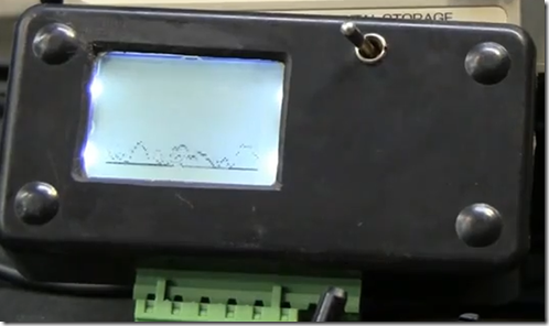
O funcionamento é muito simples, e a tela LCD Nokia 3310 funciona muito bem para esse fim, o desenvolvedor ainda acrescentou dois potenciômetros, um faz o atraso para a amostragem na base de tempo e outro para reduzir as tensões, enquanto eles estão abaixo de 3 volts, que é a tensão de operação do Arduino.
A parte ruim, ou seja os contras deste projeto é que ele só mede tensões de até 3 volts, mas se você deseja medir tensões maiores você deve adicionar um atenuador ao circuito,ou seja, na entrada da ponta de prova do osciloscópio. Outro problema deste osciloscópio Arduino é que a entrada analógica mostra apenas as tensões positivas.
Lista de componentes do Osciloscópio com Arduino
Arduino Mini Pro
tela LCD Nokia 3310/5510
R1-R2 Potenciômetro linear 10Kohms
Bateria 9 Volts
Abaixo o Sketch do Osciloscópio Usando Arduíno
/*
###########################################################
  Title:       Arduino Oscilloscope
  Purpose:     Use a Nokia 3310 GLCD screen with the arduino
  Created by:  Filear k. see Fil eark. com for more info.
  Note:        Please reuse, repurpose, and redistribute this code.
  Note:        This code uses the Adafruit PDC8544 LCD library
###########################################################
 */

#include "PCD8544.h"

// pin 3 - Serial clock out (SCLK)
// pin 4 - Serial data out (DIN)
// pin 5 - Data/Command select (D/C)
// pin 7 - LCD chip select (CS)
// pin 6 - LCD reset (RST)
PCD8544 nokia = PCD8544(3, 4, 5, 7, 6);

// a bitmap of a 16x16 fruit icon
static unsigned char __attribute__ ((progmem)) logo16_glcd_bmp[]={
0x06, 0x0D, 0x29, 0x22, 0x66, 0x24, 0x00, 0x01, 0x87, 0x00, 0x27, 0x6C, 0x20, 0x23, 0x06, 0x00,
0x00, 0x00, 0x00, 0x00, 0x00, 0x10, 0x10, 0x00, 0x03, 0x00, 0x00, 0x00, 0x00, 0x00, 0x00, 0x00, };
#define LOGO16_GLCD_HEIGHT 16
#define LOGO16_GLCD_WIDTH  16

int channelAI = A0;      // select the input pin for the Oscilioscope
int scaleYAI = A1;       // select the input pin for the Y (horizontal) potentiometer
int scaleXAI = A2;       // select the input pin for the X (Vertical) potentiometer

int delayVariable = 0;   // define a variable for the Y scale / delay
int xVariable = 0;       // define a variable for the x scale
int yCtr = 0;            // define a variable for the y counter used to collect y position into array
int posy = 0;            // define a variable for the y position of the dot
int myArray[85];         // define an array to hold the data coming in


void setup(void)
{

  nokia.init();

  // turn all the pixels on (a handy test)
    nokia.command(PCD8544_DISPLAYCONTROL | PCD8544_DISPLAYALLON);
    delay(500);
  // back to normal
    nokia.command(PCD8544_DISPLAYCONTROL | PCD8544_DISPLAYNORMAL);

  // show splashscreen
    nokia.display();
    delay(500);
    nokia.clear();
}

void loop()
{
  delayVariable = analogRead(scaleYAI);
  delayVariable = (delayVariable/50);
  xVariable = analogRead(scaleXAI);
  xVariable = (xVariable/22);

  for(yCtr = 0; yCtr < 85; yCtr += 1)   // the for loop runs from 0 and < 85, it fills the array with 84 records
    {
      posy = analogRead(channelAI);       // read the value from the sensor:
      myArray[yCtr] = (posy/xVariable);   // scale the value based on the x scale potentiometer
      delay (delayVariable);           // scale the y collection of data using the delay from the y potentiometer
    }

  yCtr == 0;                           // set the counter to zero so we can use it again
  nokia.clear();                       // clear the LCD screen so we can draw new pixels

  for(yCtr = 0; yCtr < 85; yCtr += 1)  // for loop runs 84 times
    {
       nokia.setPixel(yCtr, myArray[yCtr], BLACK); // draw the 84 pixels on the screen
    }

  nokia.display();                     // show the changes to the buffer
  yCtr == 0;                           // set the counter to zero so we can use it again

}
Vídeo do Osciloscópio Arduino em funcionamento
Uma dica é blindar o osciloscópio com uma caixa para evitar interferências indesejadas. Se preferir faça o download da documentação Sketch e biblioteca ou verifique o projeto na fonte.